GNSS Positioning Techniques
Global Navigation Satellite Systems Positioning Concepts
At their core, Global Navigation Satellite Systems (GNSS) are a timing system where all satellite clocks are precisely synchronized. GNSS satellites broadcast coded signals at exact times, and the user’s receiver collects the coded messages. The receiver estimates the time it takes for each signal to travel from the GNSS satellite antenna to the user’s antenna. Once the time of flight is estimated, the distance is calculated by multiplying the time of flight by the speed of light to arrive at a distance measurement in metres from each satellite to the user’s antenna.
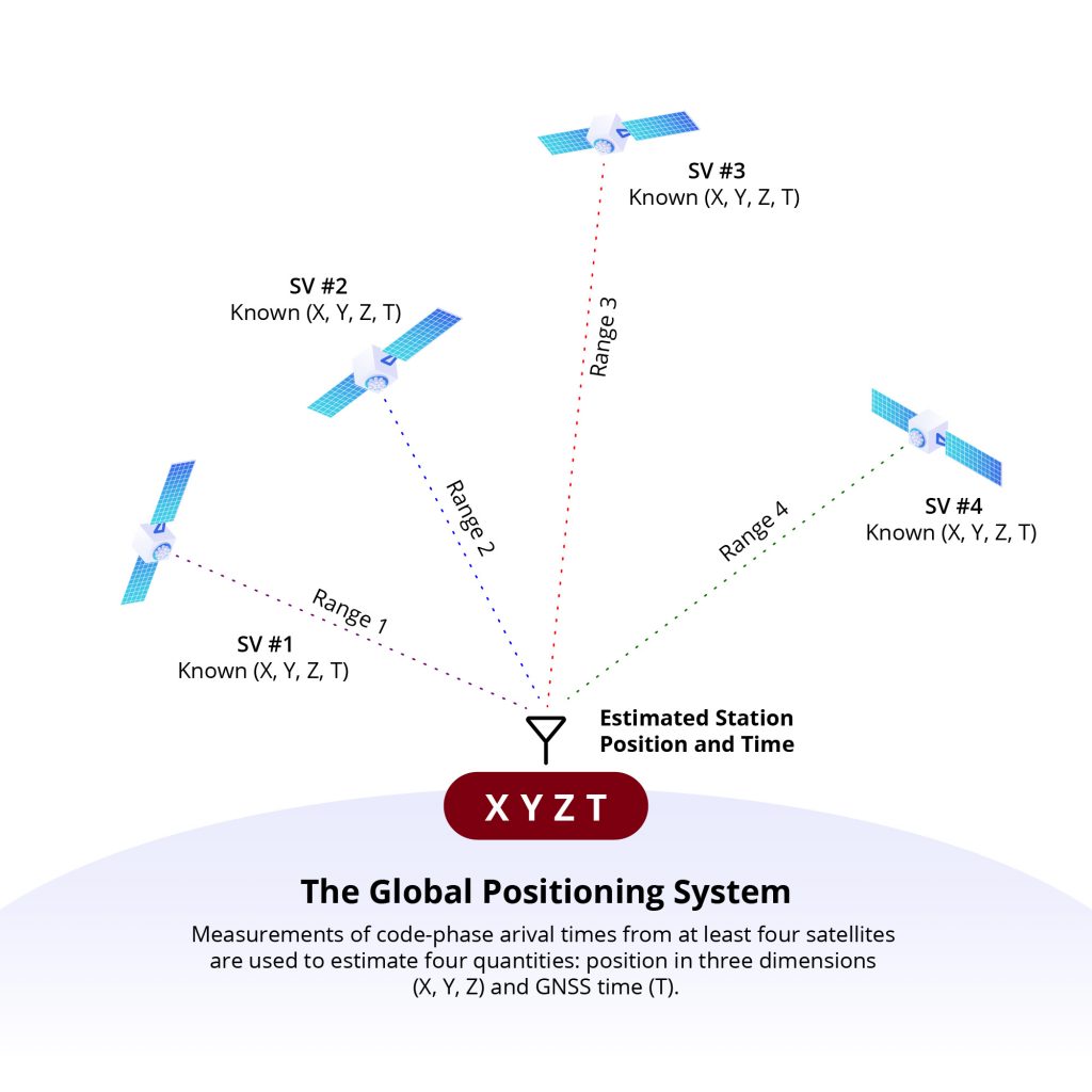
GNSS satellites also broadcast ephemeris messages that enable the user’s GNSS receiver to determine the satellite’s antenna position when the measurement signal was broadcast (in cartesian X, Y, Z coordinates). The receiver must measure the time delay (range) from at least four satellites to estimate the ground antenna position. With four range measurements, the GNSS receiver estimates the antennas X, Y, Z coordinates and T, the receiver’s time. Figure 1 shows the intersection of the four measured ranges.
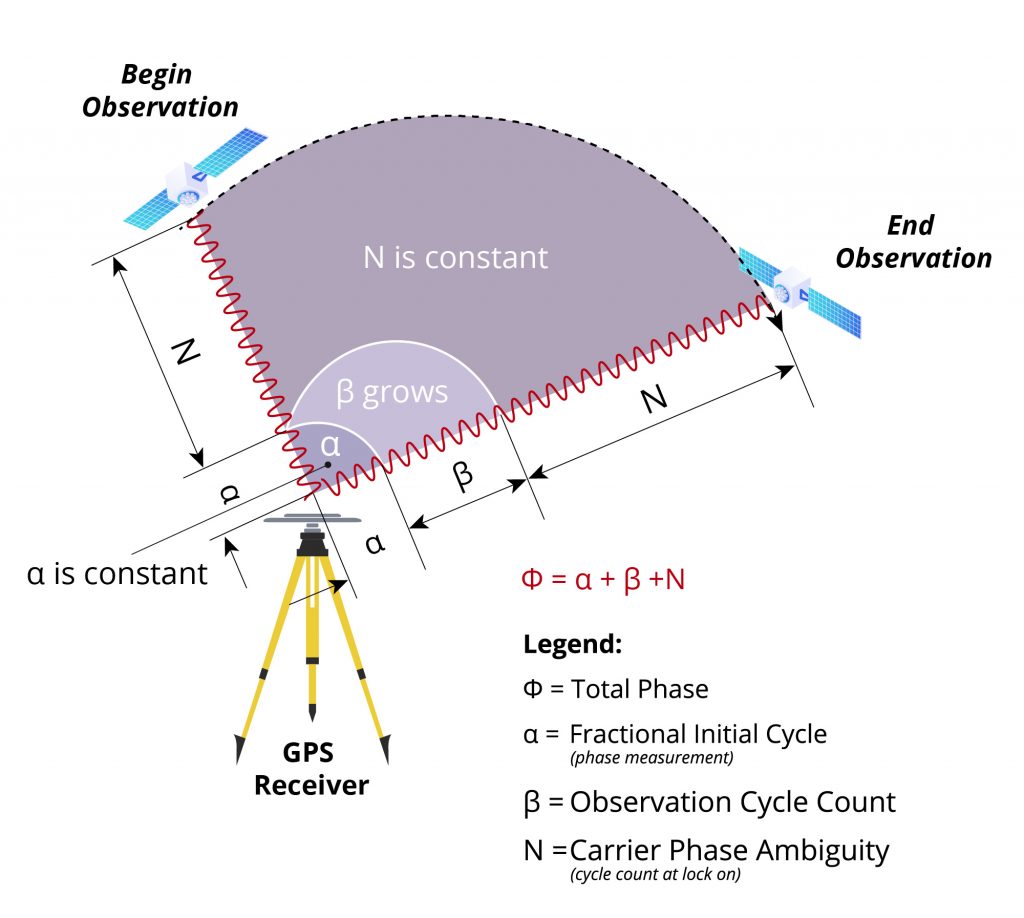
Only the code measurements have been considered in the conceptual description of GNSS systems above. In practice, both the code and carrier phase measurements are used to enable high-precision GNSS positioning. Code and phase measurement accuracy is affected by: systematic errors (described later), the local multipath environment, antenna, and GNSS receiver quality. A typical cell phone GNSS antenna and receiver pair enable range measurement accuracy at the 3-5 metre level. On the other hand, geodetic and survey-grade antennas (VeraChoke®, VeraPhase®, VeroStar® and Accutenna®) and receiver pairs can produce code measurements with approximately 1.0 – 0.3 metres accuracy. Phase measurements can be accurately measured (to better than 100th of a wavelength) in the case of GPS L1; phase measurements have a wavelength of approximately 19cm and can be measured with a precision of about 1-2 mm. However, the exact number of wavelengths from the satellite antenna to the user’s antenna (N) is unknown and must be estimated. Figure 2 shows phase measurement over time and the unknown parameter N that must be estimated.
Carrier phase measurements enable the estimation of high-precision GNSS positions. To derive high precision position estimates atmospheric effects and other systematic errors must be eliminated or minimized. Two positioning techniques are commonly used. One employs a local differential method: Real-Time Kinematic (RTK). The other uses a wide-area satellite tracking network (typically spanning the earth) that enables the estimation of atmospheric and satellite corrections, this technique is called Precise Point Positioning (PPP).
Real-Time Kinematic Positioning
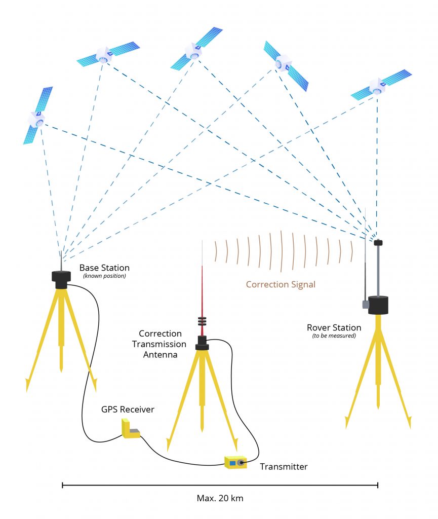
Local differential GNSS or Real-time Kinematic GNSS techniques use differencing techniques to eliminate or minimize systematic errors such as satellite clock and orbit errors, troposphere and ionosphere effects. Local differential techniques require a base station with known coordinates and a rover for which the coordinates are estimated. The base station broadcasts its coordinates and the GNSS observations. The rover receives the base station coordinates and satellite observations (ranges and phase measurements) and estimates its position. This technique can provide very accurate positions (2-3cm) for short baselines. Figure 3 shows the typical RTK architecture.
Precise Point Positioning
Precise Point Positioning (PPP) is a technique that employs corrections to the satellite’s broadcast orbit and satellite clock. In addition to satellite errors, the GNSS signal is delayed or advances as it travels through the atmosphere and must be corrected. Typically, a PPP correction service broadcasts information that enables the computation of an ionospheric correction. A tropospheric correction is estimated using a reference model. High precision (cm to dm) PPP requires a high-precision multi-frequency GNSS receiver and antenna. High-accuracy PPP typically estimates the ionospheric and tropospheric delays. A PPP correction service consists of the following components: ground-based tracking stations, analysis software to calculate the orbit, clock and ionospheric corrections and a method of distributing the modifications to users. Figure 4 shows the typical architecture of a PPP correction system.
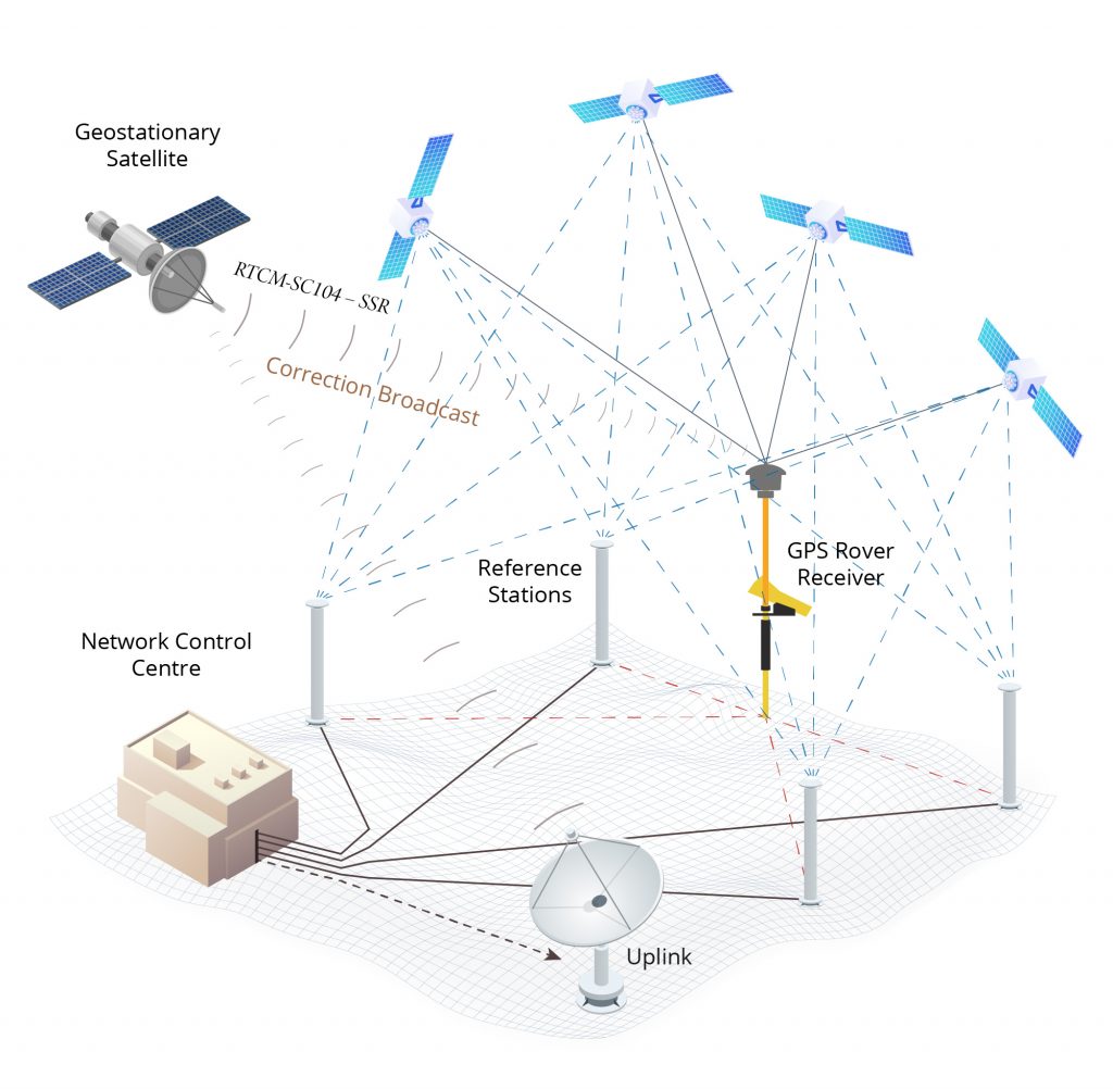
Figure 4 Precise Point Positioning (PPP) System Architecture
All GNSS constellations and signals require a high-quality GNSS antenna. Even the best GNSS receiver cannot produce accurate and precise results without a high-quality precise antenna.
For more information, visit: https://www.meted.ucar.edu/training_module.php?id=1216