
GNSS Antenna Radio Frequency Characteristics
Antenna Element Gain
The radiation gain of a GNSS antenna element is an important parameter that directly contributes to the quality of the global navigation satellite signals received by the antenna. A good quality system will provide high signal to noise ratio (C/N0) values which are function of the ratio of the antenna element gain over the noise temperature of the system. Higher antenna gain together with a low noise figure will produce measurements with optimized C/No.
Antenna Gain Roll-Off
The gain of antenna rolls of at the Frequency band edges (limited by the antenna bandwidth) and the radiation pattern of the antenna as a function of elevation angle. Typically, the gain of an antenna is the highest at zenith (highest elevation angle) and decreases to lower levels at the horizon (lower elevation angles).
Axial Ratio
GNSS signals are transmitted by the satellites as right hand circularly polarized (RHCP) (visualize a circular spiral signal leaving the GNSS satellite antenna and travelling through space), the GNSS receive antenna should also be RHCP, and strongly reject signals of the opposite rotational sense (LHCP). Axial ratio is a measure of this rejection normalized to reception of the RHCP (“co-polarized”). The axial ratio is the ratio between the semi major and semi minor axis. For a perfect antenna both values would be the same (i.e. equal to 1) or 0dB, over all azimuth and elevation angles and all frequencies within the antenna bandwidth.
Bandwidth
GNSS spread spectrum signals are transmitted over a range of frequencies within a given band. For example, the GPS L1 signal has a bandwidth of +/-10.23 MHz centred at 1575.42 MHz.
Group Delay
Group delay is an instrumental error that starts at the GNSS satellite. As a conceptual example consider that you have an oscillator creating a base frequency and then there are frequency multipliers that generate L1, L2 and L5 frequencies. Next the codes are added to each frequency. As a result of this process all codes are not necessarily generated and broadcast at exactly the same time and as a result there will be a group delay between the L1 CA code and the L2 C code and all codes. This instrumental delay also occurs in GNSS antennas, antenna cables and receivers.
Ground Plane
An antenna ground plane is a flat or close to flat horizontal surface that serves as part of the antenna. The ground plane plays a major role in the performance of an antenna’s radiation pattern and gain. TWI provides ground planes for most of its antennas.
G/T Ratio
The G/T ratio is a figure of merit that characterizes the performance of an antenna. Where G is the antenna gain in decibels at the receive frequency and T is the noise temperature in kelvin units. T is not the physical antenna temperature as such but is a summation of the antenna noise and the radio frequency chain noise temperature from the antenna connection to the output.
Low Noise Amplifier (LNA) Gain and Noise Figure
GNSS satellite signals are broadcast in space and travel approximately 20,000 Km from the satellite antenna to the user’s antenna. As a result of the broadcast power and the distance traveled the signal received by the antenna is very weak (barely a whisper) and must be amplified. All amplifiers add noise to the amplified signals, and a key requirement for a GNSS antenna LNA is that, across the full bandwidth, the LNA gain is flat with minimal additional noise (quantified in the Noise Figure parameter). The antenna is often remotely sited and the LNA is required to have sufficient gain to more than compensate for the cable losses, and to limit the system noise figure to that of the LNA alone.
Multipath Rejection
Ideally GNSS signals travel directly form the GNSS satellite to the user’s antenna. However, the local environment can cause GNSS signals to bounce off hard surfaces such as buildings, water, road surfaces etc. and these bounced signals will affect the receiver’s ability to accurately track the GNSS signals. Reflected signals change, at least in part, from right hand circular polarization to left hand circular polarization at odd order reflections. TWI antennas employ several techniques (Accutenna technology, ground planes, choke rings) to reject left hand circularly polarized signals and as a result can minimize the affects of multipath.
Noise Figure
Noise Figure is defined as the ratio of signal to noise ratio at the input to an amplifier and the signal to noise ratio at the output. Keeping the noise figure as low as possible enables the GNSS receiver to fully process the GNSS signal and estimate accurate and precise position and time estimates. Noise occurs in all components in the chain between the antenna, amplifier, antenna cable and receiver. A good noise figure is typically less than 2 dB.
North Marker
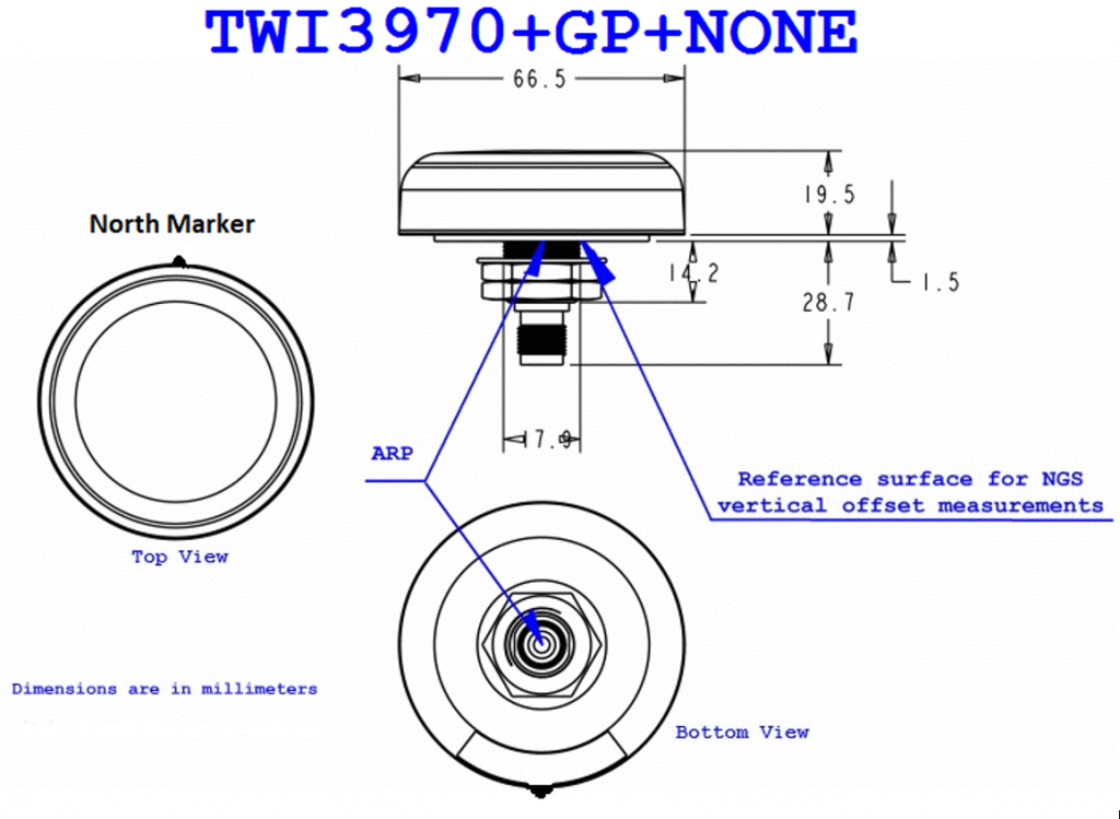
In high precision GNSS positioning, antennas are calibrated, and their Phase Center Offset (PCO) and Phase Center Variation(PCV) are measured. The PCO and PCV are estimated either in an anechoic chamber or using a calibration robot. The calibration process refers the PCO and PCV to the antenna’s North marker and then to the antenna’s reference point (ARP), as shown in the figure below. In practice, calibrated antennas are always installed with the antenna’s north marker pointing north. This enables the user to correct the observed phase measurements (applying PCV corrections) and apply the PCO to the estimated position to finally determine the coordinates of the ARP.
A secondary benefit of the antenna North marker is that the antenna assembly process is more repeatable and precise as the antenna can only be assembled one way. This ensures that when the PCO and PCV corrections are applied, the user will measure an unbiased (accurate) and precise position estimate.
P1dB
P1dB is the output power level when the amplifier gain, deviates from the normal linear gain specification by 1dB.
Phase Centre Offset
The Phase Centre Offset (PCO) is the location relative to the antenna reference point (ARP) where the antenna collects the GNSS satellite’s signals (electrical energy). Typically, the PCO for each frequency is defined. For GPS typically both the L1 and L2 PCO values are given.
Phase Centre Variation
Phase Centre Variation is the measure of how much the phase centre varies as a function of the elevation angle and azimuth of the received signal. Typically, only geodetic and survey grade antennas are calibrated to this level.
VSWR
Voltage standing wave ratio is the amount of power that is reflected back into the antenna (from the antenna cable) upon transmission out of the antenna. GNSS antennas and antenna cables are impedance matched at 50 ohms. A VSWR ratio of one indicates that there is an ideal match between the antenna, antenna cable and GNSS receiver.